
| Facility Information |
| User Guide |
| PAC |
| Beam Time Operation |
| RIBF User Group |
| Collaboration |
| Seminars |
| Links |
| Archives |
|
Rare-RI Ring (R3)
 |
||||
Configuration
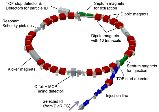
The injection line consists of ten quadrupoles and one dipole, in addition to two septa for injecting the particles. The ring consists of six magnetic sectors, each consisting of four dipoles. This dipole is a rectangular magnet with a radially homogeneous magnetic field. Ten one-turn trim-coils are installed in the two outer dipoles of each magnetic sector. The kicker magnets are located in the position of the phase advance 3π/2 from the injection septa, and the extraction septa are located in the position of the phase advance 3π/2 from the kicker magnets.
Plastic scintillation counters are installed in each straight section to check the injection trajectory. Carbon-foil + MCP detector and resonant Schottky pick-up are used to get a revolution frequency information from a circulating particle with and without destruction.
TOF start/stop detectors can be installed at just before/after the ring, respectively. ΔE-E detectors for particle identification can also be installed in a chamber after extraction.
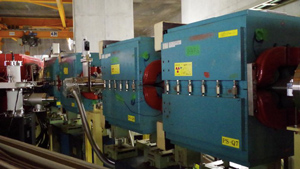
Ten Quadrupoles and one dipole of the injection line
| Quadrupole | Dipole | |
|---|---|---|
 |
 |
|
| Type : laminated | Type : laminated | |
| Bohr radius : 50 mm | GAP : 80 mm | |
| Length : 600 mm | Radius of curvature : 4.045 m | |
| Max. current : 1000 A | Max. current : 3000 A | |
| Coil / pole : 12 turns | Coil / pole : 20 turns | |
| Max. field* : 0.6 Tesla | Max. field : 1.7 Tesla | |
| Bending angle : 15.7 degrees** |
* It corresponds to the pole-tip magnetic field.
** Bending angle can be adjusted by the bump coil.
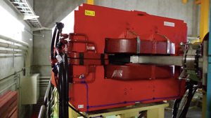
Septum magnets
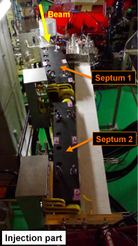 |
Septum 1 | Septum 2 | |
|---|---|---|---|
| Type : | Lumped | Lumped | |
| Gap : | 45 mm | 45 mm | |
| Radius of curv. : | 5.05 m | 13.0 m | |
| Max. current : | 2200 A | 2200 A | |
| Coil : | 20 turns | 8 turns | |
| Bending angle : | 12.7 degrees | 5.3 degrees | |
| Max. rigidity : | 6.0 Tm | 6.0 Tm | |
Extraction part also has two septa. |
|||
Specifications of the ring
| Circumference : | 60.35 m | |
| Length of straight section : | 4.02 m | |
| Momentum acceptance* : | 1 % | |
| Max. injection energy : | 170 MeV/u | |
| * It corresponds to the isochronous adjustable range. Possible momentum width of extraction is about 0.5 %. |
||
| For a beam energy of 170 MeV/u | ||
| Revolution frequency : | 2.65 MHz | |
| Transition γtr : | 1.18 | |
| Betatron tune : | Qx 1.18 , Qy 0.93 | |
| Max. Beta function : | βx 8.4 m , βy 11.9 m | |
| Dispersion of straight section : | 7.0 m | |
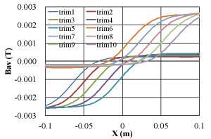
Trim-coils
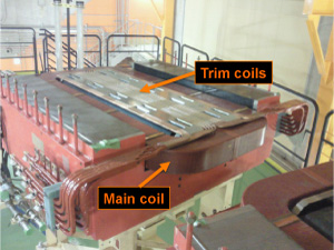 |
Type : | Copper hollow conductor |
| Size : | 6 mm x 6 mm Φ3 mm | |
 |
||
| Right hand of figure shows the average magnetic field generated by each trim-coil excited at 300 A. | ||
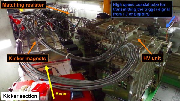
Fast-kicker system
Block diagram of fast-kicker system
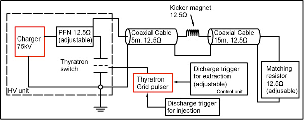
| Characteristic impedance : | 12.5 Ω |
| Thyratron switch : | CX1171 made by e2v |
| Max. charging voltage : | 75 kV |
| Max. repetition for injection : | 100 Hz |
| Interval between injection and extraction : | |
|
700 μs |
|
9.5 ms |
| (adjustable in 10 ns step.) | |
| Type of kicker magnets : | Distributed constant twin type |
Specifications of the kicker magnet
 |
 |
| Capacitance of cell : | 350 pF |
| Inductance of cell : | 100 nH |
| ※ Additional capacitances are used for impedance matching. | |
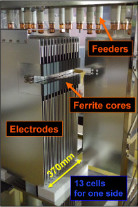
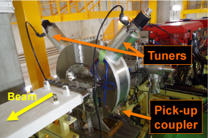
Resonant Schottky pick-up
 |
|
||||||||||||||||||
| * Cavity is filled with air and electrically isolated from the beam tube by a ceramic insulator. | |||||||||||||||||||
This system was able to aquire the revolution frequency information from one particle of Kr.
Information of the detectors
1.Timing detector for circulating particles
- Carbon foil + MCP*
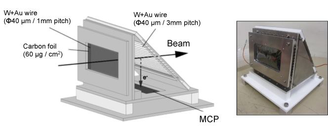
| Thickness of C-foil : | 60 μg/cm2 |
| Size of C-foil : | 100 mm x 50 mm |
* For details, please see Ref. [4].
2. TOF start/stop detectors
A T-shaped plastic scintillation counter is used for TOF start detector. For TOF stop detector, a standard plastic scintillation counter is used. For the TOF measurement, these detectors can be used or they can be replaced by the user's detectors depending on the requirements of the experiment.
3. Detectors for particle identification.
An ion chamber or Si detector will be used for ΔE measurement. Such as NaI can be used for total-E measurement.
Vaccum system
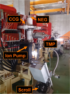 |
For the rough pumping
|
||||||||||||||
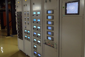 |
Photo of the control system
|